You will lear how to make Piston in Autocad. This is on categories advanced tutorial. You can learn tutorial step by step and more easly. so let us start.
Time for something more complicated. A piston.
Open the Part Design workbench and create a new document.

Start sketching on the XY plane. Set left top corner at (0,0). The piston diameter is 75 mm, so top horizontal line should be 37.5.

You can see complete sketch above. If you cannot see dimensions of piston rings grooves, here is table (ring grooves enumerated from top):

Create a revolution around Vertical sketch axis. The effect should looks similar to real piston :)

Select bottom face (as the above sketch).

Now, create a new sketch on the previously selected face.

Click Create an edge linked to an external geometry and select the biggest circle.
Select face as above. It will be base for a sketch and a revolution.

Hide Revolution using [Space]. You should see the projected circle. It is only reference like construction lines, so you have to draw additional geometry and constrain it with circle. I draw two arcs, and two vertical lines. In other way you can draw circle, two lines and use trimming tool.

Create a 48 mm long pad. Probably it should have reversed direction.
Next operations are similar.

Select face as above.

Create two rectangles. You can use an vertical construction line and symmetry constraint.

Remove material by a 57 mm long pocket.

Now you need some piston pin support. Select bottom piston deck face (as above) and create a new sketch.

Use external constraints tool to make circle projection and hide the Pocket.

Create two symmetrical shapes - every from three lines and arc.

Extrude pad 30 mm long.

Select face as above. It will be base for a sketch and a revolution.

Create two external constraints from vertical edges and hide the Pad001.

Create a geometry using external constraints.

Revolve it and check effects.

Reopen the sketch and add symmetrical geometry.

At the end revolution should look like above.
 Select face as above. It will be base for a sketch and a revolution.
Next step is a hole for piston pin. Create a new sketch on he XY plane.

Create a geometry with horizontal construction line.

In the revolution dialog select Axis: Sketch axis 0.

After all you still can change construction line position. Adjust vertical distance to -30 (or 30 - depends from the sketch orientation).

Go to the Part workbench and make Revolution002 mirror. Use the YZ plane.
 Then select (use [Ctrl]) the Revolution002 and Revolution002 (Mirror #1) and do a boolean fuse.

Next you can select piston solid (probably Revolution001) and fusion from previous step (Fusion). Create a boolean cut (difference) of them.

The piston is almost done.

You can remove some material and create space for rotating crankshaft counterweights. Select side face and create pocket.

I recommend radius 90 mm and distance 162 mm. Model with 105 and 180 mm respectively would be invalid, from manufacturing point of view.
 And we have our piston! Let's create some blueprints.
Open the Drawing workbench. Multi views creation is now possible.

Create a new Page using Insert new drawing. Select last shape (Pocket001) and use Insert an orthographic projection of a part in the active drawing. You have to define projection type:

Beside wizard, manual single view creation is possible.


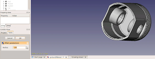
Select edge or edges and then click on fillet icon.
Radius can be always changed in the the Task view.
 If you do not see edge, right-click on a shape and select Appearance... Then change Flat lines to Wireframe.
Now the tutorial How to Draw and Modeling Piston in Autocad has been finished. If you need any tutorial to improve your skill in autocad please visit other tutorial on this blog. Ok thanks for coming.
By:

Open the Part Design workbench and create a new document.

Start sketching on the XY plane. Set left top corner at (0,0). The piston diameter is 75 mm, so top horizontal line should be 37.5.

You can see complete sketch above. If you cannot see dimensions of piston rings grooves, here is table (ring grooves enumerated from top):
| Height [mm] | Width [mm] | |
| Gap | 7 | - |
| Groove 1 | 1.75 | 3 |
| Gap | 4 | - |
| Groove 2 | 2 | 3.6 |
| Gap | 4 | - |
| Groove 3 (oil ring) | 3 | 4 |

Create a revolution around Vertical sketch axis. The effect should looks similar to real piston :)

Select bottom face (as the above sketch).
External constraints.
The external constraints have been introduced in recent versions of FreeCAD. Now you can create projections of some external geometries (eg. edges) to the sketch and use ones as references. Try find icon with line and blue box Create an edge linked to an external geometry.
Now, create a new sketch on the previously selected face.

Click Create an edge linked to an external geometry and select the biggest circle.
Select face as above. It will be base for a sketch and a revolution.

Hide Revolution using [Space]. You should see the projected circle. It is only reference like construction lines, so you have to draw additional geometry and constrain it with circle. I draw two arcs, and two vertical lines. In other way you can draw circle, two lines and use trimming tool.

Create a 48 mm long pad. Probably it should have reversed direction.
Next operations are similar.

Select face as above.

Create two rectangles. You can use an vertical construction line and symmetry constraint.

Remove material by a 57 mm long pocket.

Now you need some piston pin support. Select bottom piston deck face (as above) and create a new sketch.

Use external constraints tool to make circle projection and hide the Pocket.

Create two symmetrical shapes - every from three lines and arc.

Extrude pad 30 mm long.

Select face as above. It will be base for a sketch and a revolution.

Create two external constraints from vertical edges and hide the Pad001.

Create a geometry using external constraints.

Revolve it and check effects.

Reopen the sketch and add symmetrical geometry.

At the end revolution should look like above.

Next step is a hole for piston pin. Create a new sketch on he XY plane.
Sketch revolution axes.
You can use every construction line as revolution axis.
Create a geometry with horizontal construction line.

In the revolution dialog select Axis: Sketch axis 0.

After all you still can change construction line position. Adjust vertical distance to -30 (or 30 - depends from the sketch orientation).

Go to the Part workbench and make Revolution002 mirror. Use the YZ plane.


Next you can select piston solid (probably Revolution001) and fusion from previous step (Fusion). Create a boolean cut (difference) of them.

The piston is almost done.

You can remove some material and create space for rotating crankshaft counterweights. Select side face and create pocket.

I recommend radius 90 mm and distance 162 mm. Model with 105 and 180 mm respectively would be invalid, from manufacturing point of view.

Orthographic views wizard.
Open the Drawing workbench. Multi views creation is now possible.

Create a new Page using Insert new drawing. Select last shape (Pocket001) and use Insert an orthographic projection of a part in the active drawing. You have to define projection type:
- First angle (Europe),
- Third angle (United States)

Beside wizard, manual single view creation is possible.

Fillets.
Part Design fillets and chamfers work in the same way now.
Select edge or edges and then click on fillet icon.
Radius can be always changed in the the Task view.

Now the tutorial How to Draw and Modeling Piston in Autocad has been finished. If you need any tutorial to improve your skill in autocad please visit other tutorial on this blog. Ok thanks for coming.
Remember:
Fillets are hard for every CAD kernel. They often fail. Create fillets at the end of modelling if you can. By:
No comments:
Post a Comment